Physical Address
304 North Cardinal St.
Dorchester Center, MA 02124
Physical Address
304 North Cardinal St.
Dorchester Center, MA 02124

Several months ago I had a project idea that needed small, WiFi enabled, and cheap microcontrollers – lot’s of them! I immediately headed to AliExpress to find a bargain and was not disappointed to see ESP32 C3 Mini’s on sale for less than $1 each, an absolute bargain for such a powerful development board!
The ESP32 C3’s arrived in less than a week and appeared to work perfectly, I uploaded a few test sketches, LED blink, ADC-to-serial etc, all worked fine. Unfortunately, trying to upload LEDW (an app for controlling WS18 LED strips), proved unsuccessful, in most cases it was possible to upload the code and access the ESP32 on my home network, but the WiFi range was absolutely abysmal! A little research online quickly revealed the issue…
The ceramic chip antenna (the red component labelled C3) needs appropriate matching to the ESP and sufficient space on the PCB away from other components. Looking at the images below shows exactly why this is a major problem for some of the cheap development boards found online!

Here’s a link to the ESP32 C3 Mini’s from AliExpress, super cheap but the WiFi needs to be fixed: https://s.click.aliexpress.com/e/_oo2C2Sl
Looking at other development boards that I’ve used in the past, there’s a clear difference, these tend to follow the manufacturers recommended layout which tends to help! It’s clear to see a copper and component free area around the antenna, this is crucial!
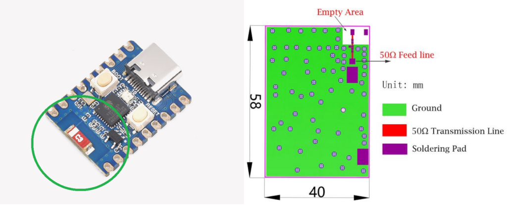
Check out the link below for the C3 ‘zero’ (shown above) which has a usable antenna and works well on WiFi without an additional antenna: https://s.click.aliexpress.com/e/_ooeF6m9
I’m not the first person to identify this issue, as you might imagine! There are a number of people complaining about the weak WiFi and a number of interesting articles exploring what can be done to rectify it… from these, I found the article by Peter NeuFeld to offer the most convenient and easy to implement solution:
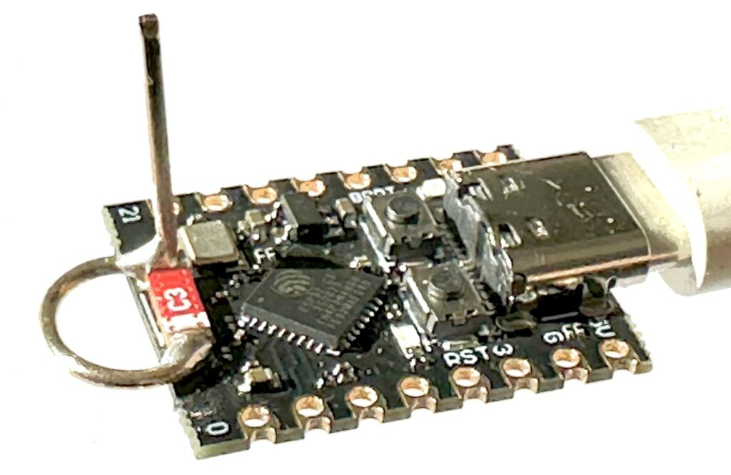
Simple quarter wave wire antenna installed directly onto existing chip antenna. Credit Peter Neufeld.
In Peters work, the vertical element is approximately 31 mm in length and the existing chip antenna effectively completes a wire loop—mechanically at a quarter of its circumference, but electrically as a λ/4 element in parallel with a λ/8 wire. It’s an ingenious design!
This is as easy as stripping the plastic coating from a length of solid core hook-up wire and bending it into the correct shape. My Youtube video shows how I made it, it’s really easy… Simply cut the wire a little longer than you need (e.g 50 mm), find a screwdriver or drill bit that has a diameter of approximately 5 mm and simply wrap one end of the wire around it to form a simple loop of 5 mm diameter. Then cut the antenna down to the correct length, I’d suggest to start a little longer than needed, something like 36 mm should do it!

Once you’ve made the antenna you need to attach it directly across the red chip antenna on the development board (the red component, typically labelled ‘C3’ – which isn’t anything to do with it being on a C3 dev board!). It’s important that the ‘free’ end of the loop is connected to the side of the antenna opposite to where the crystal oscillator is, as shown below. Then simply ensure the antenna is bent so it’s roughly perpendicular to the PCB surface and you’re ready to go!

Using two microcontrollers it’s easy to assess the performance of your new antenna, you don’t need to do any coding, the example WiFi sketches available in Arduino IDE make it super easy! In the video I used an ESP32 S3 Dev Kit as my second microcontroller, but almost any ESP with decent WiFi can be used. We’ll be using it as a test Access Point and as a test client for when your ESP32 C3 is acting as an Access Point. First let’s check the receive performance of the modified antenna, upload the WiFiScan example to the modified ESP32 C3, then upload the WifiAccessPoint sketch onto the second microcontroller.
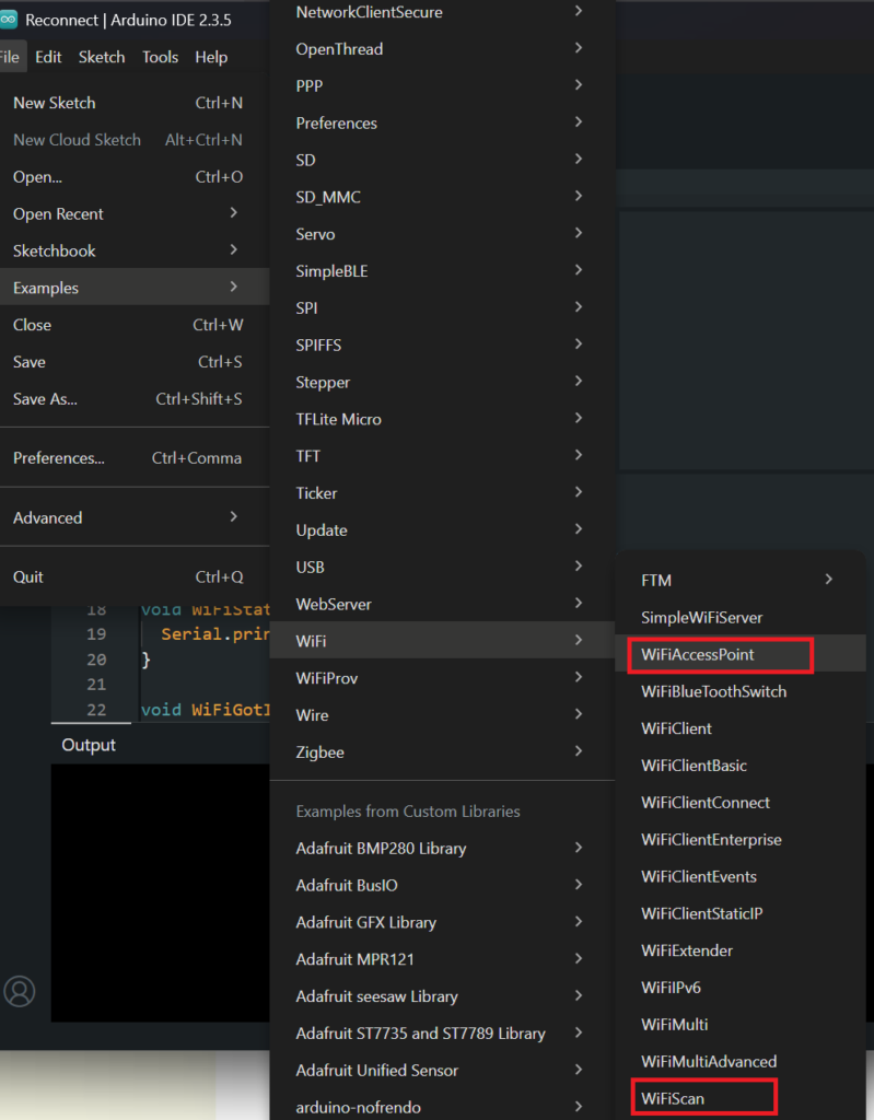
Here’s the general overview of the test I performed in video:

With your modified ESP32 C3 connected to the serial terminal in the Arduino IDE, you should see a list of nearby WiFi access points, here you should see the Access Point created by your other microcontroller. For every Access Point the RSSI should be shown, this is a value in dBm and the higher it is, the stronger the signal! I logged the RSSI of three Access Points, the ESP32 S3 located about 1.5 M away, my home router located about 1 M away, and my wifi extender located about 6 M away through several walls. First, I established a benchmark case using an ESP32 WROOM module as a client, here are the results:
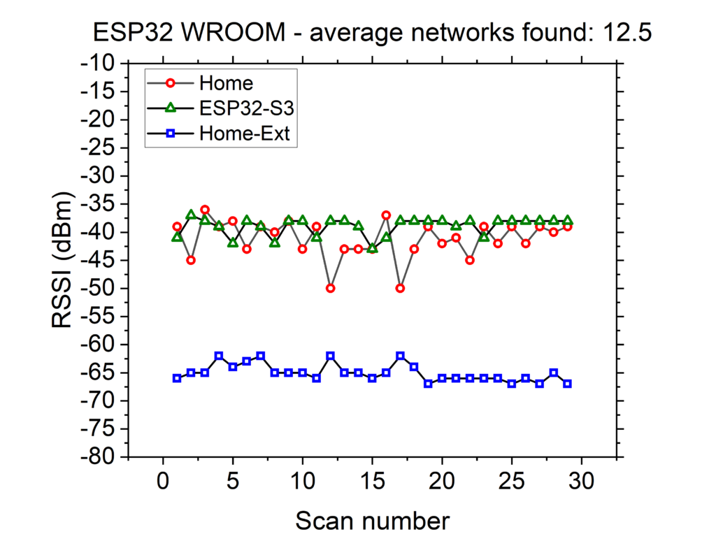
The graph above shows a benchmark case (not the original or modified ESP32 C3). As can be seen, the two ‘nearby’ access points have a strong signal, averaging around -38 dBm. The WiFi extender located several rooms away is weak, but still very usable.
The next graph shows the results for the ‘original’ unmodified ESP32 C3 mini, the z-axis hasn’t been changed, it’s clear to see how much lower the signals are!
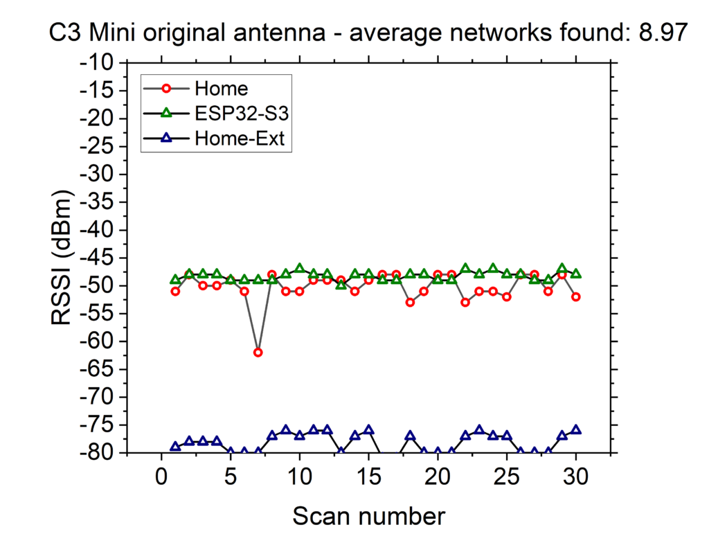
Just focusing on my WiFi extender, as this represents a typical use case for me, it’s clear that the signal is much weaker, almost 15 dBm lower than the benchmark case. Given the dB scale is logarithmic, a 15 dB difference is enormous!
Now for the modified C3 Mini with the new antenna, keep in mind that the antenna used to gather this data is not optimized and is slightly too long (around 36 mm, rather than the ideal 31 mm, this is because I want to gradually reduce the length whilst recording the transmit power for optimization, it shouldn’t make much difference to the results in this test).
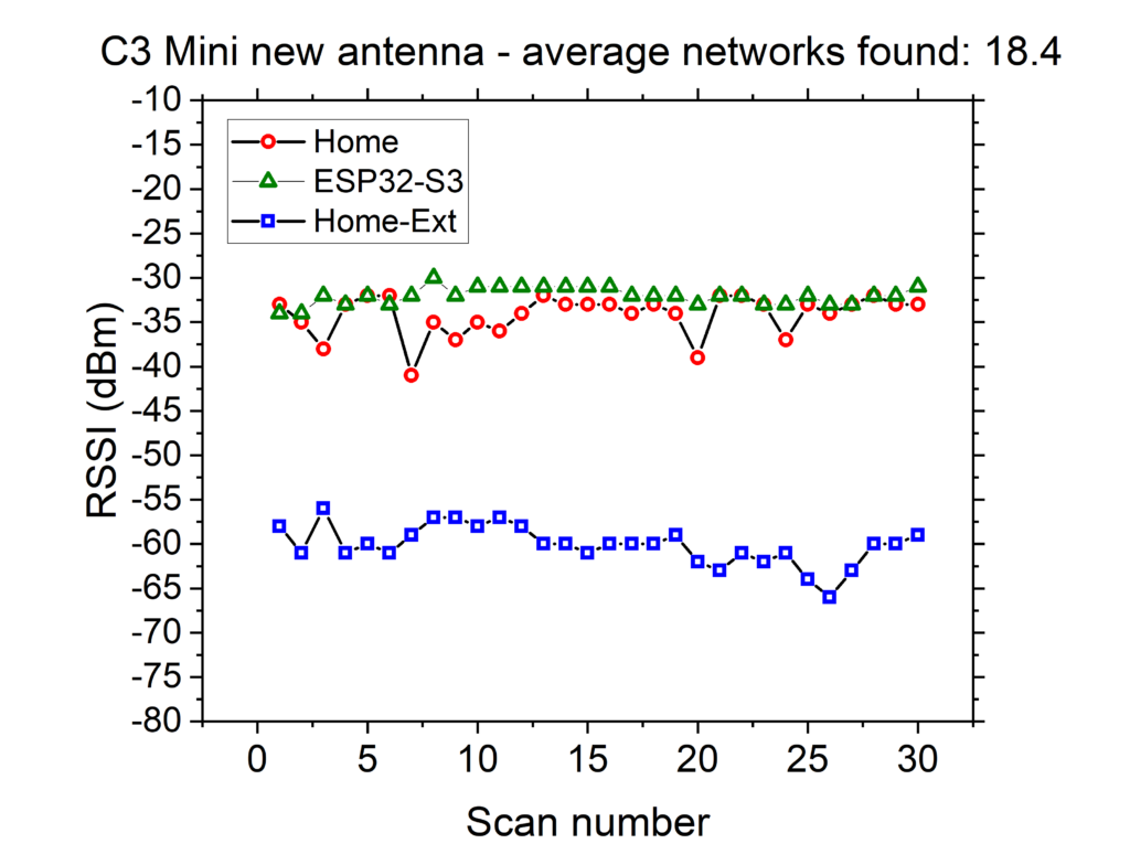
The results from the modified C3 show a massive improvement, even in the worst case scenario, the home extension is almost 5 dBm higher than the benchmark case and a massive 18 dBm higher than the unmodified C3, this is a dramatic difference. In summary, the receiver performance of the C3 using the new antenna has been significantly improved! Here’s a direct comparison showing the averages:
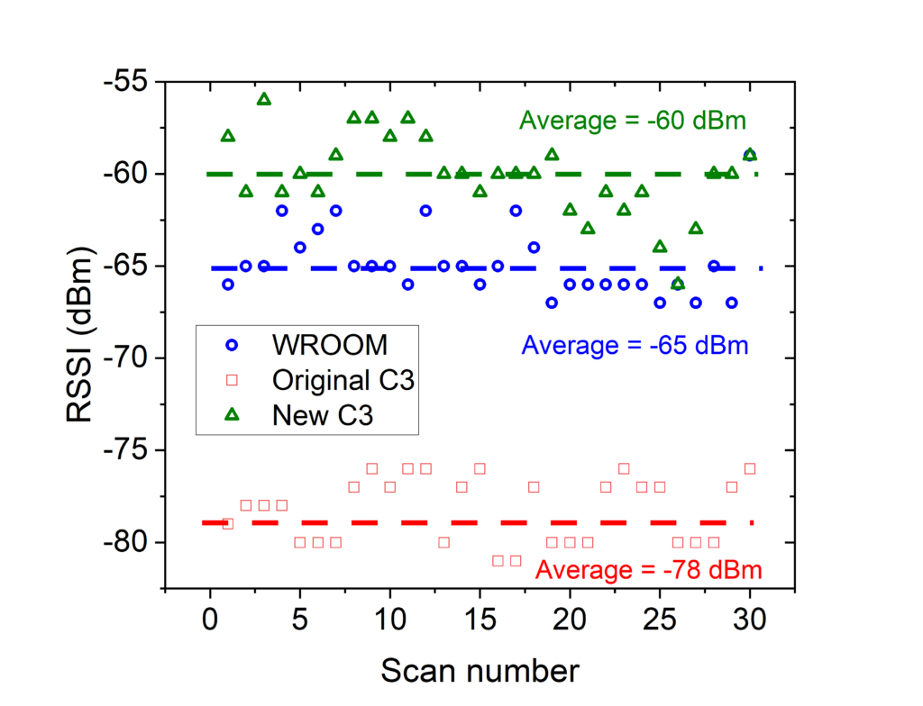
To give some context into these numbers, the chart below shows how the RSSI affects connectivity…

Now to test the transmit performance of the modified C3. This is the real test as it is relatively easy to improve the receive performance of any radio using ‘almost’ any form of antenna. To improve the transmit performance the antenna must be well matched to the transmitter. To do this I deliberately made the antenna on my C3 mini too long, 36 mm, when the actual quarter wavelength is 31 mm. I did this so I could gradually reduce the length whilst observing the transmitted signal strength to determine the optimum length.
To do the transmit test, I set up the modified C3 as the Access Point and the ESP32 S3 as the client, as shown below:

To optimize the antenna length, I started with an antenna approximately 36 mm in length and recorded the RSSI measured by the S3 around 30 times and calculated the average value. Then I cut 2 mm from the antenna and repeated the process, recording the RSSI at each length until the antenna was only 26 mm in length. Here are the results:
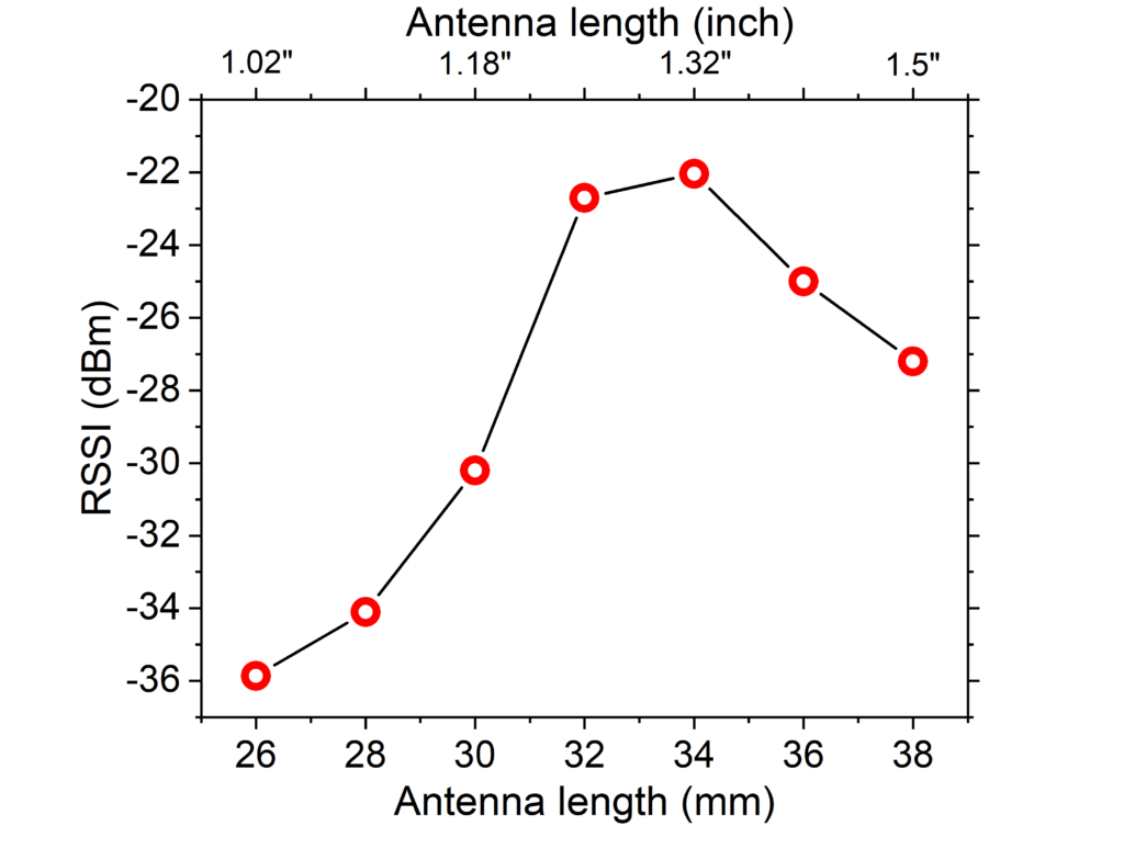
As shown above, the optimum length for the highest RSSI is 34 mm (or 1.32 inch), this is not exactly as predicted (in theory 31 mm is optimum) but it is not unexpected as antenna performance is affected by many factors including the diameter of the actual wire used and how the new antenna is influenced by the matching between the transmitter in the ESP etc. The result shows a dramatic improvement in performance, although I didn’t show the test, the original C3 with just the PCB antenna only gives an RSSI of -60 dBm under the same conditions, hence there’s almost a 40 dBm improvement – an astonishing increase!!
While the improvements gained by adding a quarter wave antenna are fantastic, making the C3 Mini usable again, it has to be said that the new antenna is quite large, it’s actually longer than the entire C3 Mini PCB! In an attempt to reduce the size of the antenna, I used some tweezers to coil the antenna into a spiral… I knew this would reduce performance but to make the C3 usable again, I only need the performance to match the benchmark case!

There’s a vast amount of research into the design of compact antennas, what I did in the video ignores ALL OF IT 🙂
This was just a quick test to see how badly coiling the antenna affects performance, as shown in the video, the RSSI drops to -44 dBm, which is definitely a drop compared to the optimum condition (-22 dBm), but it is still significantly better than the original C3 antenna (-60 dBm)!!
In this post I explain how to improve the performance of an ESP32 C3 mini by installing a quarter wave wire antenna. The gains are dramatic, easily tripling the range of the original PCB antenna. All that is required to fix the development board is a soldering iron and a length of solid core wire, it’s a no brainer as far as I’m concerned and turns my pile of useless ESP32 C3’s into a pile of highly capable microcontrollers!
Thanks again to Peter Nuefeld for the original concept, be sure to check out his blog (linked above) for more details and don’t forget to check out my Youtube video to watch how the antenna is built and installed!